Thursday 31 May 2007

Day Four - Measuring gravity using a free-fall apparatus and plotting a graph in Microsoft Excel.

Firstly, we decided on the experiment that I was going to do. We chose to do an experiment to measure gravity, g, using the free-fall method.

The apparatus was set up as shown. The experiment was first done with a large ball-bearing, and then with a smalller bearing. Basically, the bearing is held in place in the clamp at a known, measured distance, s. When you release the bearing, it falls and hits the trapdoor underneath. Everything is connected in a circuit to a timer. When the ball hits the trapdoor and the circuit is broken, the timer stops and the amount of time that it took, t, for the ball-bearing to land can be measured. This is done once more, and the lesser of the two is used. To find g, the formula 2[s/t2] is used. This is repeated at a number of different distances and an average value for gravity is found.
This was then repeated with the small ball-bearing.

The average value that I found for g was 9.6 m s-2, the true answer being 9.8 m s-2.


I then learned how to plot my results on Microsoft Excel, a skill that might come in very handy in college! This is a photo of my fully plotted and labelled graph, with distance on the Y axis and time on the X axis.


Wednesday 30 May 2007

Day Three - Soldering my first circuit and installing an operating system on a computer!


I started my day preparing to solder my L.D.R. circuit. We went back over what we did yesterday and and drew out a rough circuit diagram. I was then given all of the various components that I would be using. Once I knew what I was supposed to be doing, I started assembling all of the different parts onto the Vero board, a more complicated procedure than it sounds! After a couple of test runs(and quite a bit of time; it took a lot of thought!!), the circuit was ready to be soldered. I then began to solder all of the components into place.

However, when I had finished everything and supplied my little circuit with the 9V power supply that it needed, my L.E.D. wouldn't turn on when I blocked the L.D.R.! We discussed the problem and we guessed that there might have been a problem with either the L.E.D. or the transistor. It was very possible that I might just have supplied the L.E.D. with a little bit too much heat when I was soldering it onto the Vero board!! So, either the L.E.D. burned out or I had short-circuited it! We went back and took out the transistor. Then, the L.E.D. These were then replaced with new parts and the circuit was tried out again. It worked perfectly this time...finally! When the circuit was connected to a source of power(the battery), the L.E.D. stayed off because the L.D.R. was resisting the flow of electricity. When the L.D.R. was covered and no light could get through, the L.E.D. turned on because their was very little resistance in the circuit.

Here is photo of my fully functioning circuit!


For the last part of the day, we installed an operating system on a computer and also took a quick look inside. A new hard drive also had to be installed before re-booting. This is a photo of our newly installed software running successfully!!

Tuesday 29 May 2007

Day Two - More Snap Circuits and learninig how to solder circuits to a Vero Board!

I started off my second day by being shown some basic circuits and by being told how they were assembled. Then, I was shown how to de-solder from a Vero board. I was given a sample circuit and my task was to completely de-solder and dismantle it. To the right is a picture of all of the equipment that I was using.
Then, I had a chance to try out soldering! I soldered a few wires and one resistor onto a Vero board, which was really cool!To the left is a photo of the front of the Vero board after I had finished my soldering.


This is a close-up photo of the back of the Vero board with all of the soldering clearly visible(if you zoom in a bit!!).

After lunch, I was meant to be doing some work with a computer, installing an operating system and taking a look inside but instead, that was put off until Day Three and I did some more Snap Circuits.
My first experiment demonstrated the principles on which a street lamp works. The circuit was set up with a lightbulb and a L.D.R. When the L.D.R. was covered or brought into darkness, resistance would become very little and the lightbulb would turn on, just the same as how, once it gets dark at night, the street lamp turns on automatically. This is a photo of that circuit. I also did other small circuits involving light and a L.E.D. previously in order to prepare for tomorrow's proper circuit.

My next Snap Circuit was a little bit disappointing; after expecting to hear a montage of noises from a jungle monsoon or something, all that I got was tap-tap-tap.. This experiment was to create 'electronic rain'. Basically,the rain began when the switch was turned on and its speed could be varied with the resistor.

Luckily, my final experiment, 'Crazy Music IC', was a lot more exciting. This was a pretttty big circuit and was the most advanced that I have done. The adjustable resistor which can be seen at the top-left of the photo was set to the far-left position and the switch was turned on. This caused the relay's contacts to open and close quickly, shorting the music IC to the ground. This caused the sound level to fluctuate amusingly..!
I finished my day by doing some more work on my blog.

Monday 28 May 2007

Day One - Snap Circuits and posting my Blog!

I am a 5th Year L.C.V.P. student studying in St. Joseph's Secondary School in Tulla, Co. Clare. For my work experience, I have chosen to come to the Science Department in the University of Limerick. I will be spending a week here with the Physics and Chemistry technicians.

On my first day, I learned a little bit about circuits and a bit about managing and creating a blog site. As I couldn't arrive into the college until later than I expected, I didn't have that long a day. Firstly, I met the different people that I would be spending time with. I was then shown around the main Physics building and brought into various labs. For my last two hours, I did some work with Snap Circuits.

The first experiment that I set up was to create a Musical Doorbell which could be turned on and off with a switch.


My next experiment was a bit less basic and used quite a large circuit. The expreriment was to create a music and alarm combo. After turninig on the switch, the music and a siren could be heard together. By pressing the press switch, the siren changed to a fire engine sound. Also, covering the photoresistor would stop the music, while the siren would continue.


Another small circuit that I made was one to create a bomb sound. This was a simple circuit containing a switch, a speaker, a L.E.D. and a smaller integrated circuit. When the switch was turned on, a bomb sound was created and the L.E.D. lights flashed.


My final experiment was the most advanced. The aim of this experiment was to use a solar panel to make music. The circuit was set up as shown, with the meter, (M1), set to the LOW scale. The meter was used to show when the solar panel could supply enough current to operate the music. This was indicated by the reading being at seven or higher. When the switch is turned on, the music starts. When the music stopped, clapping my hands made it recommence.

For the last part of the day, I learned a little bit about how to set up and manage a blog site, and also how to create my own blogs from the University website.

Friday 4 May 2007

Day 5


My last day here was a little less intensive. More of a clean-up day. To start with, I finished my work on the I.S.C. Argo. Later I went to one of the labs for a demonstration of the laws of gravity-we used a vacuum pump to suck the air out of a glass tube. Inside the tube were a penny, and a feather. When the tube was turned upside down, before the vacuum was applied, the penny predictably fell much faster. The feather after all, was being resisted by air. After the vacuum was applied, air resistance didn't matter, and so the feather fell as fast as the penny. Weird stuff, physics...


Following that I cleaned up my blog a little-adding a few photos and text, before getting to work on today's post.

You probably can't read this picture, but basically it's the graph I constructed to display the results of my previous experiment on the acceleration of gravity on two objects of different mass. It charts Time(x) against Distance(y), and gives a value for gravity.The formula used was d=at^2/2. I also received a small tutorial on Paintshop Pro, which was used to display these graphs.


This is the glass tube used for penny/feather experiment. The clips at the bottom prevent air from getting once the vacuum has sucked it out.


Thursday 3 May 2007

Day Four

Today was mostly spent on snap circuits. Some of the them were quite complicated, as you can see. Among the electrical contraptions I made were buzzers, lights, various noises and detectors, all triggered by an unlikely mechanism- water, touch, light, darkness, sound, even blowing at them. Construction was the hard part of course. Though the diagrams were simple enough to understand, it felt a bit like jenga, stacking pieces on top of each other. In the end, the projects look like miniature cities.
Later I looked at a piece of software concerning space launches. It contained a wealth of information about everything from the storage of liquid hydrogen, to a description of the power supply in Russian vessels.


This is one of the complicated circuits I made. It converts light, from a photo resistor, into noise.


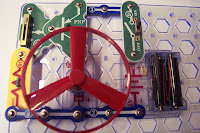
This circuit includes a fan. With the introduction of a variable resistor, I can make it go a different speeds. With a slight change in construction, I can make it suck in, or blow out air. To the left is the fan stationary, and below that, is the fan at full speed.

To the left is the space simulator. You can see my carefully constructed craft, the I.S.C. Argo. The whole thing certainly gave me a lot more knowledge about spacecraft.

Wednesday 2 May 2007

Day Three

I started today working on circuits, proper ones with crocodile clips and voltage etc. I soldered my own resistors on, and tested the amount of resistance they offered, both alone, and together in the same circuit. Naturally I recorded the results.


Resistors are actually a much more complicated subject than you might think - they're colour coded, and require a certain amount of calculation to find out how much resistance to a current they will give. As well as using maths to calculate resistance, one can also use the more hands-on approach, which requires some apparatus, and a formula or two. Basically you hook up a current with resistors to a voltmeter and an ammeter, thus allowing you to measure the voltage and current present, and also, with the help of a formula, the resistance to the current.


This is most of the apparatus used, including meters, power Supply, circuits, etc.


After that I got to watching an operating system being installed, and I happen to be typing on the very computer where it was installed. So obviously it went grand.

That's the P.C. with the system installed.

Tuesday 1 May 2007

Day Two

Day two began with a little work on snap circuits. This involved the construction of building a Light Controlled Lamp.
The circuit to the left shows the bulb lighting as the photoresistor isn't blocked.


When the photoresistor is blocked the bulb turns off! This showed me that the resistance of the photoresistor decreases as the light increases.


Following that I went to work on a thorough experiment to measure acceleration due to gravity. For this, I used two metal spheres of differing sizes, and apparatus which allowed me to monitor how long it took for the spheres to hit the ground after being released in the air from a measured distance.

Later I used Microsoft Excel to display my results and plot them on a chart. As well as the distance the spheres were dropped from, I also measured the time it took for them to hit the ground three times, and got the average of each of these measurements. After a few calculations, my accuracy was confirmed when the answer I got for gravity proved very close to the correct figure of 9.8 m/s/s.